Current State of the Art for New Cable Systems
Taking advantage of recent advances in technology for terrestrial optical transport networks, today’s long-haul subsea cable systems make use of optical wavelengths carrying a 100 Gbit/s (100G) signal with Polarization Multiplexing Quadrature Phase Shift Keying (PM-QPSK) modulation format, wavelength multiplexing, coherent detection, digital signal processing and soft-decision forward error correction. Optical fibers exhibit lower attenuation and larger effective area than 10 years ago for decreasing fiber nonlinearities and meeting the optical signal-to-noise ratio requirements imposed by 100G wavelengths. Optical repeaters based on Erbium-Doped Fiber Amplifiers (EDFAs) offer an optical spectrum of about 35 nm, while more recent Raman optical amplification technology enables spectrum exceeding 50 nm and the multiplexing of up to 150 wavelengths per fiber pair.
All these advanced photonics technologies are available and combined today for the design of subsea long-haul transmission infrastructure. As a result, new subsea cable systems can offer a total capacity of 10 to 15 Tbit/s per fiber pair, or up to 90 Tbit/s assuming a cable equipped with 6 fiber pairs, on transoceanic distances. 90 Tbit/s capacity is equivalent to transmitting 2,829 uncompressed HD films in a single second, a tremendous increase compared to the rate of 10 words per minute for telegraphic cables!
Implementing New Subsea Routes
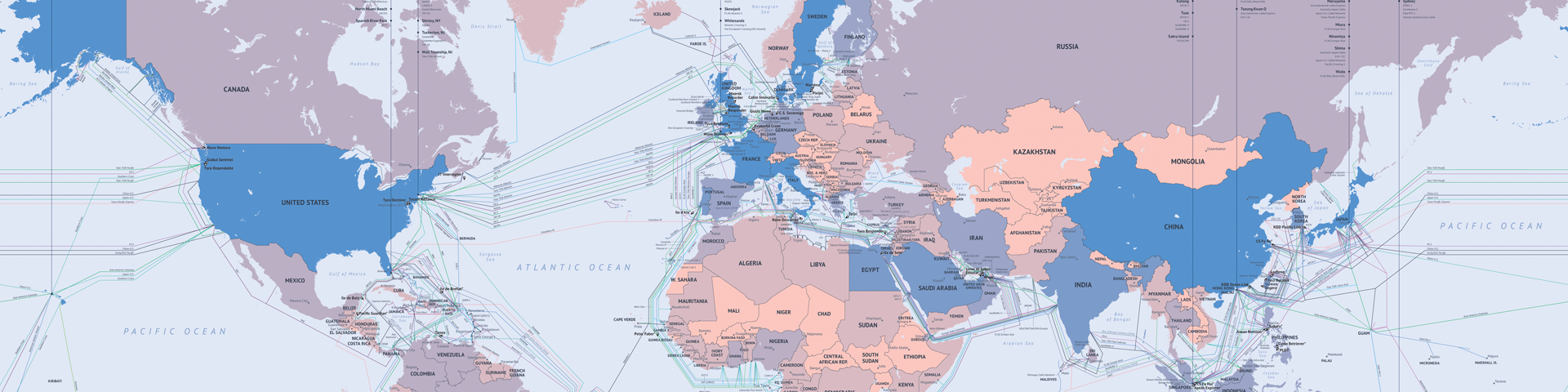
Until the beginning of the 2000s, most of the subsea routes have been built in the northern hemisphere with the noticeable exception of a few cables to Australia and New Zealand, a subsea cable system linking several coastal countries of the African continent, a similar type of cable system configuration for the south America, and a cable system between Brazil and Europe. The map below (from TeleGeography) represents the subsea cable systems already deployed or planned in the short term.
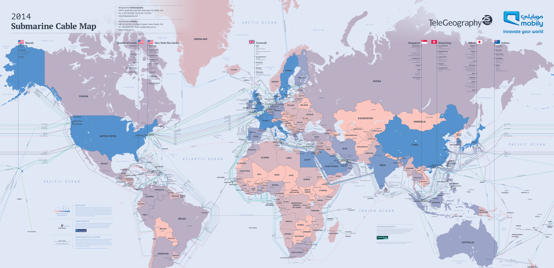
Today there is a need to offer additional and more direct connectivity to emerging countries in the southern hemisphere as illustrated by the advent of several subsea cable systems along both west and east African coasts, and new proposals to connect Brazil directly to Africa or Europe without going first to North America. Different reasons and strategies support the development of these new routes. To mention a few of them, geopolitical reasons can dictate the need to avoid a specific country for landing or transiting, the obsolescence or high failure rate can make operators walk away from some existing systems, the search of short latency can govern the deployment of more direct routes, and the desire for higher resiliency of international connectivity can drive operators to develop new, physically diverted routes.
One example of new subsea routes driven by the quest for lower latency is offered by the projects for deploying subsea cable systems connecting, e.g., Japan to the UK via the Arctic Seas instead of following the traditional route via Singapore, India Ocean, Red Sea and Mediterranean Sea. Similarly to equivalent project for new shipping routes (e.g. the Northwest Passage, which is a sea route connecting the northern Atlantic and Pacific Oceans through the Arctic Ocean, along the northern coast of North America), the objective is to offer services with lower latency: while it takes today roughly 230 ms for a packet to go from London to Tokyo; the new cables are expected to reduce this by 30% to 170 ms by virtue of a much shorter run.
Evolving from Point-to-Point Links to Meshed Networks
The traditional approach that has prevailed for many decades was to deploy point-to-point subsea routes with Submarine Line Terminal Equipment (SLTE) in the cable landing stations. The current trend is to place the line terminal equipment in the Point of Presence (PoP), which is the access point of capacity for telecom customers, or in the data center (DC). PoPs and data centers are generally not located on the seaside in the cable landing station, but further inland. With today’s technology, it is possible to avoid the physical demarcation and optical discontinuity at the point where the subsea cable lands and to offer an all-optical PoP/DC-to-PoP/DC path. In the cable landing station reside still Power Feed Equipment (PFE) for remotely powering the submerged optical repeaters, and Reconfigurable Optical Add Drop Multiplexers (ROADMs) that pass thru the PoP/DC-to-PoP/DC optical signals. When configured with multiple degrees, ROADMs can interconnect with other cable landing stations by dedicated terrestrial or subsea links.
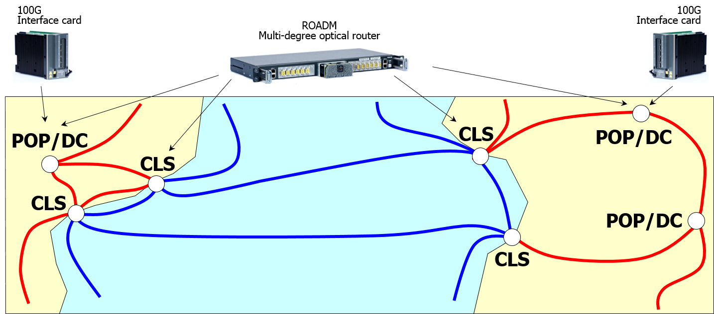
For complex configurations involving multiple cable landing stations and multiple subsea routes, multi-degree ROADMs in cable landing stations and 100G interface cards in PoPs/DCs for the optical wavelengths traveling throughout the network will be used to transmit the signals with a high level of protection/resiliency. Whatever the complexity of the network configuration and the diversity of physical routes, whether terrestrial and submarine, the objective is the same: ensure end-to-end connectivity within a unified network with the smallest number of demarcation points or at least with no impact on the transmission distance. The higher the number of routes available in the network, the higher the resiliency with respect to multiple cable cuts or equipment failures. In order to enable fast and reliable protection/restoration, different options for the control plane are proposed by equipment vendors. Meshing multiple terrestrial and subsea routes to offer resilient unified PoP/DC-to-PoP/DC connectivity is key for capacity consumers, especially in areas that are sensitive to earthquakes (like south east Asia) or that form some kind of geographical bottlenecks (like Egypt).
For comments or questions, please contact us.