Second Post of a Series of 4
This post is the second of a series of 4 about the information rate transported by submarine cable systems. The first post of this series presented in a simple way the Shannon limit that drives the ultimate subsea cable system capacity. This post examines the various multiplexing options that can be put at work for increasing subsea cable system capacity and lowering the cost per transported bit as well. The third post will look at some technologies that can be used for approaching the Shannon limit with the objective of maximizing the capacity transported by a single communication channel (in our case, a single fiber core). Finally, the last post will review the most recent and significant results from laboratory demonstrations and field trials so one can get a good view of what will be feasible, capacity wise, in the short-and mid-terms.
Options for Increasing Subsea Cable System Capacity
A very common strategy throughout communication history to increase the information rate transported by any communication channel, regardless its technology, has been to use multiple dimensions for parallelizing/multiplexing the data to be transported. Focusing on optical fiber communication, we have several multiplexing dimensions to play with for increasing subsea cable system capacity:
- Time – Increasing the baud rate (number of symbols per second) linearly increases the system capacity.
- Multi-Level Modulation Format – Increasing the number of bits per symbol (e.g. QPSK modulation format encodes 2 bits per symbol, 8QAM 3 bits per symbol, 16QAM 4 bits per symbol) also linearly increases the system capacity.
- Wavelength – Increasing the wavelength (or carrier) count linearly increases the system capacity as well. The number of wavelengths is governed by their spectral spacing (itself dictated by the signal spectrum due to modulation format and pre-propagation spectral shaping) and the submerged optical repeater bandwidth.
- Polarization – In commercial coherent products, two orthogonal States of Optical Polarization (SOPs) are combined and launched into the fiber core. These two SOPs effectively double the information rate transported by a single optical carrier. In the short term the SOP count will stay at 2 and there is no improvement to be expected there.
- Space – At the cable level, the space multiplexing dimension is the number of fiber pairs, assuming single-mode, single-core fibers. If multi-core fibers are considered in the mid- or long-term, the fiber capacity will be multiplied by the number of cores in each fiber (each core will be considered as an independent communication channel). If multi-mode fibers suitable for long-haul transmission are offered in the future, each spatial mode will be considered as an independent communication channel, and the fiber capacity will be increased linearly with the number of spatial modes.
The first three multiplexing dimensions (time, modulation level and wavelength) are governed by the Shannon limit as they are related to a single communication channel. As exposed in the previous post, the multiplexing of two orthogonal States of Optical Polarization (SOPs) allows to double the capacity and spectral efficiency achievable with a single fiber pair.
Today the transmission reach enabled by multi-core and multi-mode fibers is limited because multi-core/multi-mode fiber characteristics are worse than state-of-the-art commercial single-mode fiber. As a result, high-speed optical transmission with high Spectral Efficiency (SE) over transoceanic distances has been practically achieved so far using the combination of digital coherent technology, light’s various degrees of freedom, and advanced single-mode fiber featuring large effective area and ultra-low-loss for lower fiber nonlinearities and lower span loss (resulting in lower optical noise accumulation).

Total Subsea Cable System Capacity
The total subsea cable system capacity can be expressed in a very simple way, using all the multiplexing dimensions above:
Cable capacity = Baud rate x Number of bits per symbol x Number of State of optical polarization x Number of carriers x Number of (bidirectional) fiber cores (1)
For the sake of clarity, Number of (bidirectional) fiber cores equals the total number of fiber cores divided by 2. Another way to express the total subsea cable system capacity is the following relationship, which involves the spectral efficiency (which is a measure of how efficiently the optical repeater bandwidth is utilized by the optical transport technologies – see our first post of this series):
Cable capacity = Spectral efficiency x Repeater bandwidth x Number of (bidirectional) fiber cores (2)
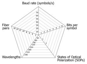
Using expression (1), pentagon shapes can be used to build radar charts that display this multivariate data in  the form of a two-dimensional chart of five quantitative variables represented on axes starting from the same central point. Practically speaking, we can play in the short- to mid-term with the baud rate (as allowed by optoelectronics and CMOS technologies), the number of bits per symbol (as allowed by Digital Signal Processing – DSP – speed), the number of carriers (as governed by the carrier spectral occupancy and the repeater bandwidth) and the number of fiber/amplifier pairs (as driven by the electrical design of the subsea cable system).
Evolution of Total Subsea Cable System Capacity
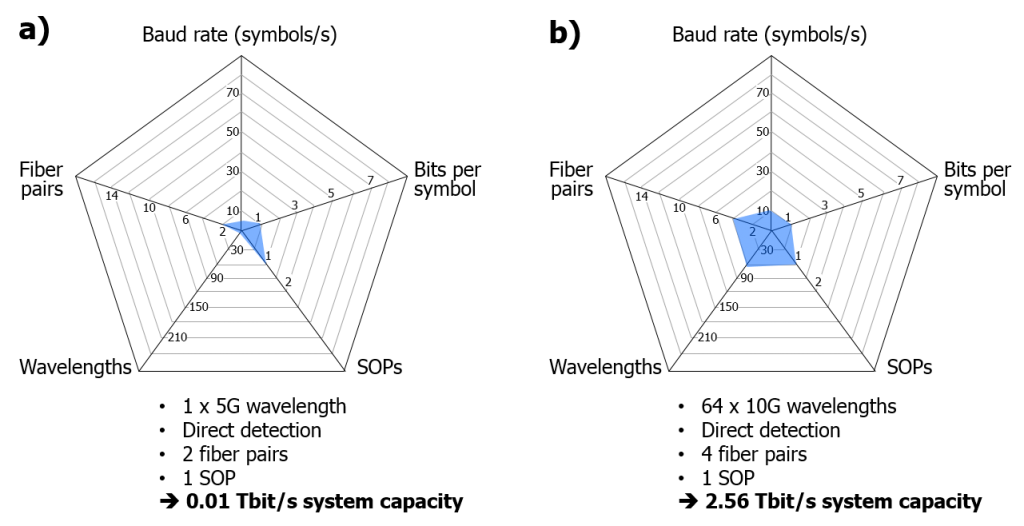
The two figures below show how the total capacity transported by subsea cable systems has been, and will be, increased over time. The area of the blue shapes gives only a rough idea of this capacity but does not intend to be strictly proportional to it.  Plot a) is representative of the first optically-amplified subsea cable systems as deployed in the 90s (like TAT-12/13): they were designed for single-wavelength operation (because of the extremely narrow repeater spectrum), with a simple, binary amplitude modulation format (so 1 bit per symbol) at the rate of 5 Gbit/s; only one state of optical polarization was utilized. Total subsea cable system capacity was then 10 Gbit/s, assuming 2 fiber pairs inside the cable.
Plot b) depicts subsea cable systems typically designed between 2000 and 2005. These systems used optical repeater with wider spectrum and Wavelength Division Multiplexing (WDM) technology enabling to combine and launch multiple wavelengths (also named carriers or channels) into the same fiber core. In Plot b), 64 wavelengths are multiplexed together, while the bit rate supported by one single wavelength was increased from 5 to 10 Gbit/s. Including 4 fiber pairs, such subsea cable systems offered a total capacity of 2.56 Tbit/s.

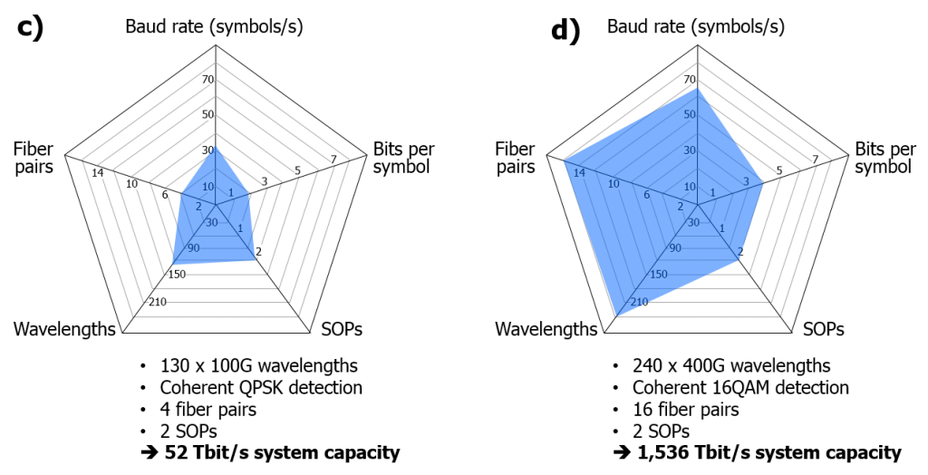
Plot c) shows the technologies put at play with the first coherent systems, as introduced around 2013 for subsea applications. The channel rate was increased up to 100 Gbit/s using faster optoelectronics components (operating at 32 Gbaud) and multi-level modulation format (QPSK in this example, with 2 bits per symbol). Due to pre-propagation signal processing and spectral shaping, up to 130 wavelengths can be packed within the Conventional (C) band of EDFA-based repeaters, spanning from about 1530 to 1565 nm. Also, coherent modulation/detection technology introduced the optical polarization multiplexing where the light beam from the laser transmitter is split into two orthogonal States of Optical Polarization (SOPs), each of them being modulated by an independent data stream. Assuming subsea cable systems designed with 4 fiber pairs, total subsea cable system capacity is 52 Tbit/s.
Plot d) illustrates what midterm subsea cable system could look like: utilization of faster optoelectronics components (operating at 64 Gbaud), 16-level modulation format (16QAM with 4 bits per symbol) and optical polarization multiplexing enabling 400G carriers, packing of 240 x 400G carriers in a wider repeater spectrum (based on C+L optical amplifier technology), and advanced electrical system design allowing the remote powering of 16 fiber pair repeaters. All these features would offer a total subsea cable system capacity of 1,536 Tbit/s, i.e. a 105 fold increase compared to the first generation of optically-amplified subsea cable systems!
The next post will examine the conditions to approach the Shannon limit inside a single communication channel (i.e. single fiber core in our case) and the practical options that are available to optical network designers for getting closer to the Shannon limit.
For comments or questions, please contact us.

