Predicting the future is not easy… That’s why astrologers and fortune tellers tend to keep their forecasts as vague as possible so everybody can find something in agreement with what they will go through or experience.

Preliminary Works
Predicting the theoretical minimum fiber loss seems quite uneasy today. 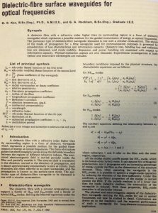 In light of recent research breakthroughs, it looks like no expert is currently putting any clear limit on the lower limit of this parameter that is key to enable ultra-high capacities over ultra-long optical reach. This has not always been the case. Charles Kao and George Hockham published a landmark paper in July 1966 proposing that optical fiber might be a suitable transmission medium if its linear attenuation could be kept under 20 decibels per kilometer (dB/km). This level of attenuation was seen as the absolute maximum figure that had to be achieved before an optical fiber system could in any way compete economically with existing communication systems. At the time of this proposal, optical fibers exhibited losses of 1,000 dB/km or more… (I.e. that one kilometer of optical fiber attenuated the light by a factor exceeding 10100!)
Stimulated by Kao and Hockham’s proposal, glass researchers began to work on the challenge of purifying glass. Careful investigation of the attenuation showed that it was largely due to absorption in the glass, caused by impurities such as iron, copper, manganese and other transition metals which occur in the third row of the periodic table. Hence, research was stimulated towards the development of purer glasses for use in optical fiber communications. In 1970, Robert Maurer, Donald Keck, and Peter Schultz of Corning succeeded in developing a length of 29 meters of glass fiber exhibiting an attenuation lower than 20 dB/km – the generally accepted threshold for making fiber optics a viable transmission technology. The 17 dB/km attenuation measured at this time deserved a “Whopee” as can be seen in the Corning lab notebook!

Optical Fiber Loss Mechanisms
Several optical loss mechanisms contribute to the linear fiber attenuation. The main ones are listed below.
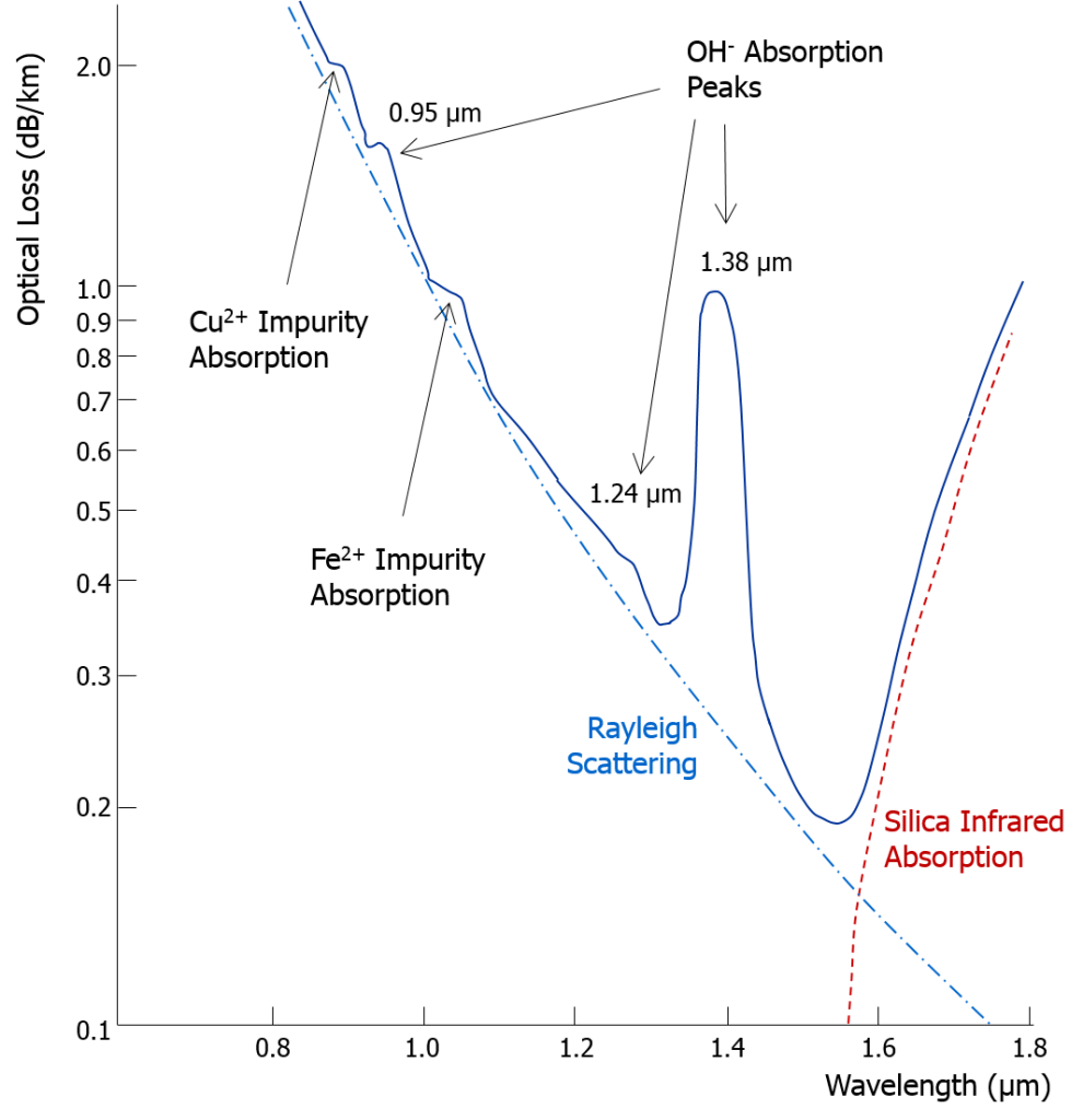
- Intrinsic Material Absorption: Intrinsic absorption is caused by interaction of the propagating lightwave with one or more major components of the fiber material. An example of such an interaction is the infrared absorption band of SiO2 shown by the red dashed line in the figure below. This loss represents a fundamental minimum to the attainable loss and can be overcome only by changing the fiber material.
- Extrinsic Impurity Ions Absorption: Extrinsic impurity ions absorption is caused by the presence of tiny quantity of metallic ions (such as Cr3+, Cu2+, Fe2+) and the OH– ion from water dissolved in glass. Some examples of attenuation from Cu2+, Fe2+ and OH– ions are shown in the figure below.
- Rayleigh Scattering: Rayleigh scattering is the main type of linear scattering. It is caused by small-scale (small compared with the wavelength of the lightwave) inhomogeneities that are produced through the fiber manufacturing process. Examples of inhomogeneities are glass composition fluctuations causing tiny changes in the material refractive index (these composition fluctuations have been constantly improved over time) and density fluctuations. Rayleigh scattering accounts for about 95+% of attenuation in optical fiber, while Mie scattering is not significant.
- Macrobending Loss: Macrobending happens when the fiber is bent from a straight deployment with some of the guided light being refracted out of the fiber. As the bend becomes more severe, more light is refracted out of the fiber. As an example, Corning® SMF-28® Ultra optical fibers should not be bent below a radius of 25 mm.
- Microbending Loss: Microbendings are the small-scale bends at the level of the core-cladding interface. These localized bends may be generated during fiber deployment or can be due to local mechanical stresses placed on the fiber, such as stresses induced by cabling the fiber or wrapping the fiber on a spool. The small radius bends that cause microbending are typically <1 mm radius.
Continuous Improvement in Fiber Loss
Over the past decades, most of the efforts were placed on reducing the impurity level (below 1 part per billion – ppb) in the manufacturing process and macrobending/microbending losses through the manufacturing/cabling/installation processes. As a result, the optical fiber loss has been constantly improved since the early 1980s with smaller OH– peaks and flatter spectrum in the third window. Please note that the vertical scale of the figure below is linear while the vertical scale of the figure above was logarithmic.
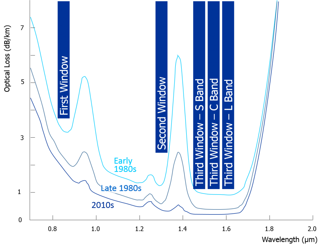
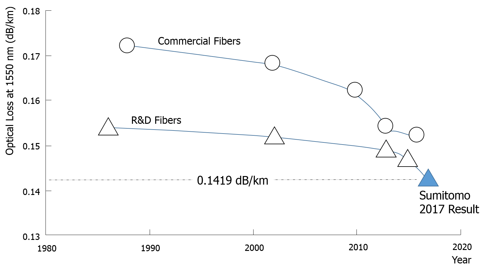
Until 2010, the lowest loss for the highest-end (and most expensive) optical fibers was above 0.16 dB/km at 1550 nm, while R&D works, mostly driven by long-haul subsea applications, demonstrated attenuation figures slightly above 0.15 dB/km. Today, the most up-to date high-capacity subsea cable systems are built with commercial optical fibers exhibiting a loss in the range of 0.153 dB/km.
Latest Technical Breakthrough
Sumitomo Electric Industries recently set a new world record for the lowest loss of optical fiber: 0.1419 dB/km at 1560 nm! At the same time the effective area is 147 µm2; this parameter is key for enabling large launched optical power (as required for meeting output optical signal-to-noise ratio requirements) and limiting fiber nonlinearities. This result was presented at the post deadline paper session at OFC 2017 conference (Paper Th5D.1).
The previous attenuation record was set by Corning (at 0.1460 dB/km) at the 2015 edition of OFC. The 0.0041 dB/km improvement between 2015 and 2017 may look not very significant but it actually matters. As exposed by Sumitomo in their OFC 2017 post deadline paper, this 0.0041 dB/km improvement means the repeater count in a 10,000 km transpacific cable system can go from 150 down to 138 (assuming 150G channels based on PM-8QAM modulation format).
One kilometer of 0.1419 dB/km fiber attenuates the light by a factor of 1,033 (100.01419, to be compared with an attenuation factor exceeding 10100 before 1970!). A 70 km span built over such a fiber in a subsea cable system will turn into a span attenuation of about 10 (in linear or logarithmic unit).
Although it is difficult to admit it, there is today no clear response about what the absolute theoretical minimum fiber loss could be.
To Conclude (About the Difficulty to Make Predictions)
Even the most successful tech prognosticators make their share of foolish predictions. Of course, it is easy to laugh at these predictions a few decades after they were expressed. But still here are two well-known samples of such worst tech predictions of all time.
For comments or questions, please contact us.
Note: Part of this post is based on elements from “An Introduction to Fiber Optics” by Ajoy Ghatak and K. Thyagarajan (1998).