Pushed originally by the OTTs, open subsea cable system approach is becoming a norm for high-capacity, long-haul subsea cable systems for this customer segment. Open subsea cable system design decouples (or disaggregates) the wet and dry plants: the wet plant is specified, designed, procured, manufactured, deployed and commissioned separately from the transmission equipment. This offers the customers the possibility to deploy the transmission equipment from the supplier of their choice (e.g. the equipment supplier for their terrestrial network) and, more importantly, to select it when needed. The selection of optical transmission technology and equipment can therefore happen a few months (just in time) before the commissioning of the wet plan, and not two years and half ahead as in the closed cable system model where the dry and wet plants were purchased at the same time from a single turnkey supplier.

Drivers to Open Subsea Cable Systems
Terrestrial/Submarine Network Convergence – Since the coherent reboot in 2010, terrestrial and submarine networks are converging, with common coherent transmission technologies and similar link design based on low loss, large effective area, high positive dispersion fiber for both applications. This technical convergence makes it difficult to justify the premium price Submarine Line Terminal Equipment (SLTE) suppliers used to charge in the past for a transmission technology that was presented as unique and way superior compared to what was used in terrestrial networks. There are still some features specific to subsea applications in order to extract the highest capacity out each of the few fiber pairs available in a subsea cable but most of the technical enhancements (like constellation shaping and tunable capacity) are led by the terrestrial suppliers who also address the subsea equipment market segment. Actually, today’s segmentation of transponder card market looks more and more like long haul (both terrestrial and subsea) on one side, and metro on the other side, while past segmentation was terrestrial vs subsea. This terrestrial/subsea long-haul equipment convergence is driving down SLTE cost because of the volume effect enabled by the terrestrial market. Large volume of equipment provides access to lower cost for components and better amortization of R&D expenses, leading to lower equipment price and more innovation.

Difference between Technology Renewal Cycles – Another big driver is the difference between development and technology renewal cycles for dry transmission equipment and wet plant (typically 2 vs 5 to 10 years). The industry knows some examples where closed systems were procured with a single contract for both SLTE and wet plant; due to delay in the wet plant building, the contracted SLTE technology (e.g. 40G in 2011) was totally outdated at the time of the wet plant RFS (2016, i.e. when 100G was the de facto standard channel rate)! Drawing conclusions from this difference between R&D cycles, some players, like the OTTs, decouple now the procurement of the wet plant from the selection and purchase of transmission equipment. Facebook recently explained at the Submarine Networks World Europe 2018 conference (20-21 February 2018 – London, UK) that the 20 Tbit/s capacity per fiber announced at the time the MAREA contract entered in force (May 2016) was not achievable then with commercial equipment! Facebook made some technology projections over the two years ahead to “bet” on which transmission technology would be ready a few months before the completion of the wet plant deployment.
Additional Drivers to Open Subsea Cable Systems – Shaping the industry is another factor favoring open subsea cable systems: some large customers (namely the OTTs) want to “force” wet plant suppliers to focus on cable and submerged equipment, leaving (terrestrial) transmission equipment suppliers to focus on fast moving technology changes in SLTE. Also, there is the desire to fully integrate submarine and terrestrial networks under a single management system for simpler, more productive operation. Last driver mentioned here is the avoidance of regeneration inside cable landing stations as offered by an open system design offering sufficient margin to enable terrestrial extensions (for instance in the case of end-to-end trans-continental links between inland data centers)

Open Subsea Cable Systems from a Networking Perspective
For end-to-end links connecting inland data centers with a stretch of water in between, the subsea cable system is viewed as a segment like the terrestrial segments on its either side. Physically, the subsea cable system is a wet segment with built-in in-line amplifiers (the submerged repeaters) all along; network topology wise, it is, however, a segment among other segments, with the only difference that the other segments are terrestrial.
This view of subsea segments has many implications, including:
- The need to achieve all-optical end-to-end connectivity to avoid signal regeneration at either end of the subsea cable system portion;
- The will to monitor and control the end-to-end link with a single network management system supporting both dry and wet segments;
- The requirement for separating out wet segment specifications and specifying its performance independently of a specific supplier’s transponder.

Typical Partner Arrangement Found in Open Subsea Cable Systems
OTTs as (Founding) Customers – In some circumstances, OTTs can “simply” board a project at a later stage, typically when the project developers (often private developers with a strong background in the subsea cable industry) are working on closing the financing of the new cable system. In this case, one OTT may be the major capacity buyer that makes viable a subsea cable system project. This happened for instance with the Hawaiki cable system between Australia and the US when Amazon Web Services decided to buy one dark fiber pair, and with AEC-1 cable system between the US and Ireland when Microsoft opted for getting one dark fiber pair on this transatlantic cable system. In these cases, the OTTs may be not very much involved in the cable system design and supplier selection process, but they provide the so-called key anchor financing to make the project happen.

OTTs as Anchor Tenant/Investor – MAREA and PLCN cable systems are two examples (among others) where the OTTs were the direct initiators and developers of the projects. OTTs like Google, Facebook and Microsoft do not want to be content with a folding seat in a telco-led consortium. Instead, they want to be large, if not the major, owners/investors in new, direct subsea cable systems that meet their connectivity needs in order to get more flexibility and higher speed in setting up connectivity/capacity. In other words, content providers may decide to build or invest in new subsea infrastructure rather than being beholden to third-party submarine cable operators with different priorities in system design and time scales in operations.
A typical model for subsea cable systems developed by OTTs looks to be based on the combination of a few OTTs (typically two) plus one carrier (who will oversee the wet plant operation and maintenance). The OTTs operate their own fiber pairs (in a way that is not much different from what they do with a terrestrial segment), add the capacity they need at the pace they need, and select optical transmission technologies independently on what the other fiber pair operators do (there is a total operational independence between fiber pairs). On its side, the carrier partner is taking care of the operation and maintenance of the subsea cable itself; for instance, the management of cable cut repairs is under the responsibility of the carrier partner, not of the OTTs.
If the subsea cable system is a little bit more complex than a simple point-to-point underwater connectivity and includes branching units with spurs, more than one carrier partner could be part of the project. Some discussions will have to take place between all the parties, for instance for the management of Power Feed Equipment (PFE) at the end of each branch and system powering in case of cable shunt fault.
Quite recently, we have seen the advent of fully private submarine cable system, owned, designed and operated by a single entity to meet its own capacity needs. The most remarkable recent public example of this new type of system is the 10,000 km Curie cable system designed and developed by Google to connect Los Angeles, California, United States and Valparaiso, Chile. This cable system is planned to enter in service in 2019. It is believed that Google is developing additional private subsea cable systems in other regions in the world.

Open, Closed and Hybrid Cable Systems
Open cable system is not a brand-new concept. The development of cross-upgrades in the mid-2000s was a first step in the direction of open systems: new optical wavelengths began to be delivered by a terminal equipment sourced from a supplier who did not install the original equipment at the time of the cable system installation. Today, even if the subsea cable system is procured and deployed in a “closed” configuration (SLTE equipment contracted and supplied together with the wet plant), operators want to be assured that their cable systems could accept additional capacity delivered by third-party equipment in the future.
What is new is the fact that some subsea cable systems are procured “naked”, with no SLTE equipment being part of the supply contract. As often, the situation is not always black and white: in some cases, you may have a hybrid configuration where some fiber pairs will be delivered by the wet plant supplier with no SLTE attached to them (open fiber pairs), while others will be delivered with SLTE connected to their ends (closed fiber pairs).
Depending on the types of fiber pairs (open or closed fiber pairs) and the needs of each fiber pair owner, distinct type of equipment can be attached to each of the fiber pairs inside the cable landing station:
- Glass-through (optical splice or optical connector) for fiber pairs owned by an operator of an inland data center, where the optical connection will be terminated (the SLTE is installed inside the data center and the optical channels are simply transiting through the cable landing station in a transparent way).
- Optical protection switches for fiber pairs whose traffic can be rerouted to other points of presence or other cable landing stations in case of primary terrestrial backhaul failure.
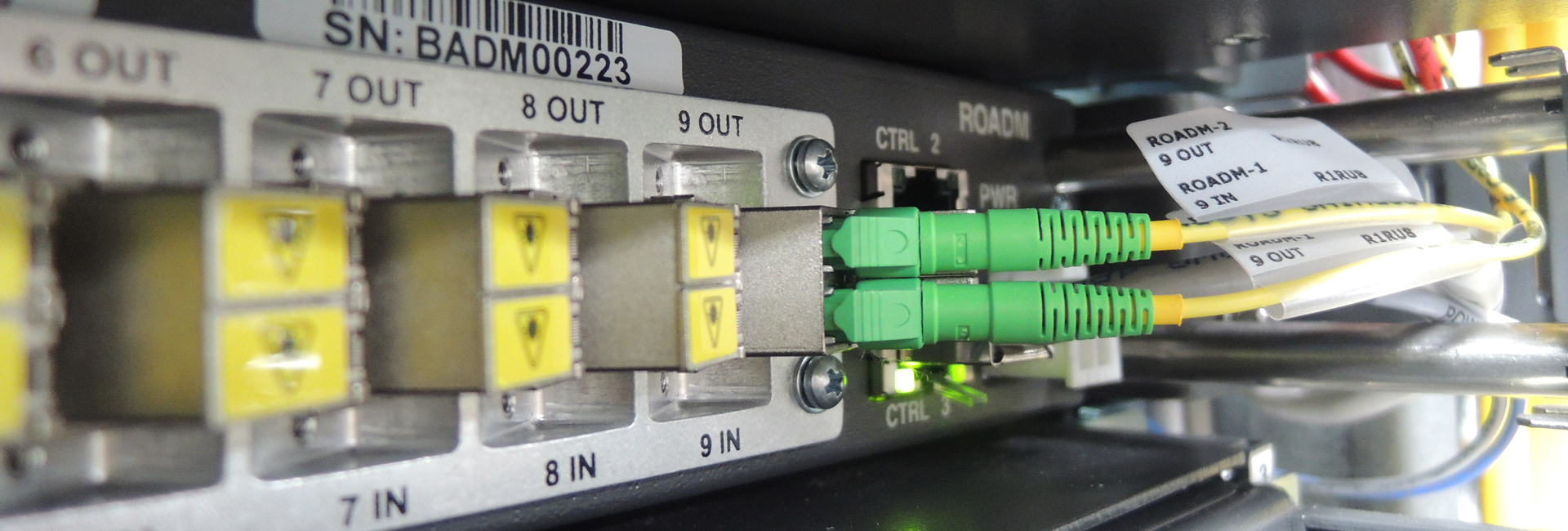
- Reconfigurable Optical Add Drop Multiplexer (ROADM, i.e. an optical switch with several node degrees – or switching directions) for fiber pairs whose part of the traffic may need to be routed to other points of presence or other cable landing stations, or to capacity customers connected locally to the cable landing station.
- SLTE equipment for fiber pairs operated by capacity wholesalers who made available the capacity services at the level of the cable landing station. This configuration requires good and diverse terrestrial backhaul connectivity outward the cable landing station.
Hybrid configuration is likely to be found in cable system owned, for instance, by a mini-consortium made of two OTTs and a carrier: OTTs’ fiber pairs are open, while the carrier’s fiber pairs are closed and equipped with an SLTE to offer capacity services at the optical channel granularity.

Commissioning
An indirect benefit stems from the open cable system scheme: the need to separate out the wet plant specifications as the wet plant must interwork with a third-party optical transmission technology. Therefore, there is a need to specify wet plant performance independently of a specific suppliers’ channel card. This “stand-alone “specification of the submarine cable is also mandatory for new network designs that connect directly inland data center to inland data center with no optical demarcation point at the beach level. In this configuration, there is no regeneration of the optical signals when the optical channels transit from the wet segment to the terrestrial segment onward to the connection endpoint located, e.g., inside the data center building.
Wet plant suppliers, including ASN and NEC, are actively working on finding an SLTE-agnostic way to test, accept and commission the wet plant. Works have been presented in several technical conferences within the past 12 months, in an attempt to extend the ITU-T Recommendation G.977 to an Open Budget Table (OBT) that can be used for commissioning open submarine cables. A future post will be dedicated to this open cable system commissioning topic.
For comments or questions, please contact us.

